Facebook Twitter RSS Feed

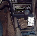
Toyota Celica Short Shift Lever


Modify the stock stick. No cost!
Result of mod: lower shift knob height. Shift throw is quicker.
*If you replace the seat-ring, it will be tighter too.
*To get the seat-ring, call Jeff Watson 1-800-327-2087,
*tell him you want the "green truck shifter gasket".
*You should ask for the "white bushing for the pivot".

Remove the black dash center cover around the stereo etc.

Remove 4 screws to remove the metal-covered rubber boot at the base of the stick.
Pull the rubber boot off.
There is a ring holding it onto the neck, pull hard, it comes off.
You don't have to remove the ring.

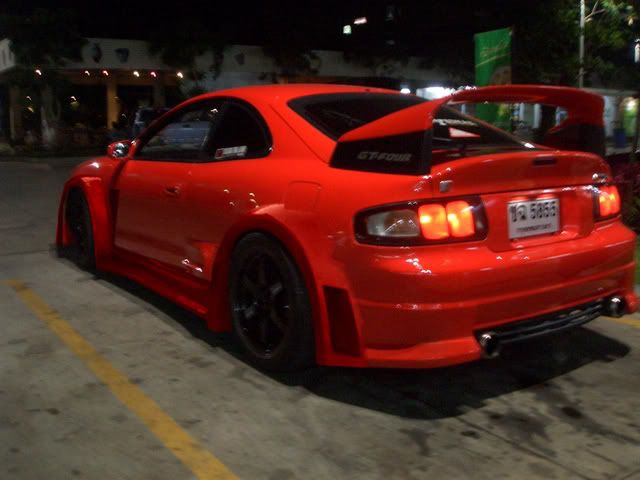
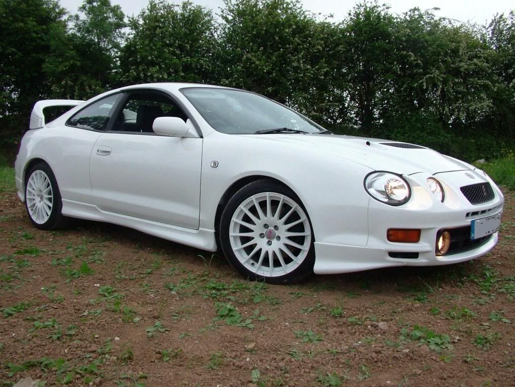
The Celica & Supra Story

'67 2000GT The origin of the Celica dates back to 1970, when the first Celica was introduced into the Japanese auto market. Toyota, known for its reliable, basic transportation, felt that its position was strong enough for it to offer its first sporty model. The Japanese economy was strengthening, and with it, the desire to drive something more exciting than the traditional, spartan Japanese automobile. This new attitude by Toyota was reflected first in 1967, with the 2000GT, a swoopy sports car built for Toyota by Yamaha. Featured in a contemporary James Bond film, the 2000GT, with its DOHC inline-6, would later become the inspiration for the Supra (the 2000GT name was also used on later Japanese Celicas and Supras) . As a sidenote, the legendary Datsun 240Z appeared in the same time frame, and may actually have been designed on the same concept as the 2000GT.

1970 Celica GT (Japan-only)
In 1971, the first Celica STs arrive in America, powered by 1.9 liter 8R-C SOHC four cylinder. A four-speed manual is the only transmission option. For '72, the larger 18R-C engine replaces the original, but the lowered compression ratio due to new emissions requirements results in an 11-horsepower loss. A three speed automatic is now available. During the 70s, sexy styling, reminiscent of early Ford Mustangs, and an eager four-cylinder enable the Celica, along with the Corolla, to solidify Toyota's position in the American market. Fun to drive, and reliable to boot, the Celica is a success.

How to Install an Aftermarket Tachometer on Toyota Celica

Installing a tachometer is very simple. It consists ot 2 simple steps: mounting and wiring. Both can be very tricky if you're unsure about what you're doing. These instructions are for any 90-93 Toyota Celica. Other Toyota vehicles may be similar.

Tools needed:

  • Screwdriver (standard and Philips)
  • Wire cutter
  • Razor blade
  • Drill
  • Drill bits

Materials needed:

  • 2 #8-32 x 1" bolts
  • 2 #8-32 wing nuts

Step 1: Mounting
I didn't mount my tachometer on the left side because there is a vent I would end up drilling through. Instead, I mounted my tachometer in the center of the car to the right of the driver. The mounting instructions are for those who wish to mount their tachometer in the center of the car.

Pull out the center vent. Unplug the clock and the hazard plugs. You will be drilling three holes: 2 for the mounting screws and one for the wiring. Simply drill 2 holes large enough for the bolts to fit through and one hole large enough for 4 wires to fit through. You'll have to drill at an angle since the windshield is in the way. Mount the tachometer to your liking.

Step 2: Wiring
On the back of the tachometer, there are 6 wires: green, red, black, white, brown, and orange. Clip the brown and orange wires. Look at the back of the clock plug; there are 4 wires. You only need to be concerned about the gray, green, and white/black wire. Splice into each wire as follows:
Power: red on tach --> gray on clock plug
Ground: black on tach --> white/black on plug
Illumination: white on tach --> green on plug
Tach wire: green on tach --> black wire ON IGNITER
Under the dash, above the steering column, there is a brass-colored fitting that hides a hole in the firewall. Simply route the green tach wire through the hole and into the engine bay. If you have an aftermarket electronic ignition, such as MSD, GM, HEI, or Crane, connect the tach wire to the tach terminal.


Toyota Celica Custom Grill

Materials:
1. Wire mesh or screen
2. Metal clips (optional)
3. Socket wrench with size 10mm(metric) socket
4. Phillps screw driver (+)
5. Flat screw driver (-)
6. Wire Cutters
7. Epoxy (super glue)
8. Wax paper-for the glue
9. Toothpick-for appling the glue

Step 1: Taking off your bumper:
The first step to making your grill is removing the bumper off the front of your car. There are 13 bolts and 4 plastic push screws. First, remove your side marker lights and turn signals. After those are off the car, lift up the hood of your car and then raise your head lights (turn your lights switch all the way on-3 clicks- and then turn it back 2 clicks or to where all the lights are off but the headlights are still in the upright position. There is a plastic fin that hides the 5 bolts on top of the bumper. Take you phillips head screw driver and remove the three (3) bolts and then the fin comes off by pulling towards you. Now, you have the bolts in sight. There are 2 in front of the right head light, 1 in the center in front of the hood lock and then 2 more on the left side in front of the left headlight. Remove all those and put them in a safe place or in a plastic bag. Now that those bolts are gone, lay on your back and look under the cars front bumper. There are 6 bolts that hold the bottom on. Take your socket wrench and remove the 6 bolts. Ok 11 down and 2 to go. On the sides of the car where the side marker lights go, there will be 1 bolt on either side, right behind where the marker light goes. Remove the 2 remaining bolts. Now, you have all the bolts off and you are ready to take off the 4 plastic locking bolts or screws. They are in the center of the car in the middle of the bumper. They are black and you will need to pry them out with your flat blade screw driver. They pop right out. Just stick the screw driver under the black plastic you see and the work the parts right out.
Now, the bumper will come off by pulling out and up on it. Just work it out off the car without forcing it. Now that you have your bumper off, you can cut your grill mesh or screen.

Step 2: Cutting the shape of your grill:
Take your screen or mesh and then cut it so it will fit in the area of the bumper. Cut it larger than the actual size that the grill will be. Make sure that you have enough room to fasten the wire screen to the back of the bumper. After you have the basic shape of the wire. Place it in or on the back of the bumper. Make sure it fits and you dont have any sharp edges sticking out. Bend the edges of the wire around the sides of the holes in the bumper. Take your metal clips and then fasten the wire to the bumper. That will give it a better hold and will ease gluing the rest of the wire.

Step 3: Gluing your grill to the bumper:
Now that you have dry fitted the grill, it is time to glue it and make it stay permanently. Mix your epoxy well and then apply it to the center of the grill. Make a decent area of glue so the wire will stick and have a good "foundation." Work your way to either sides of the grill with the glue. Make sure that you have applied the glue well enough so that the grill won't come loose when you are driving. You dont want to have to take the bumper off again. ***Let the glue dry for an hour or two.*** After you let the bumper sit, test the grill by pressing on it gently and then firmer. If the grill is strongly in place, you have done well. If it is real loose, then apply more glue and let it dry. After the grill is firmly in place, it is back to the car is goes.

Step 4: Re-placing the bumper on the car:
Reverse step 1 and put the bumper back on:
1. Slide the bumper back onto the car until the holes on the top of the bumper line up with the ones on the car frame.
2. Replace the bolts onto the car and then proceed in putting the plastic bolts back on.
3. After all the bolts are in place, replace the fin and then screw the 3 screws back in . Put the side marker lights and the trunsignals back on the car.

Then you are FINISHED!!!!!!!

You have successfully made a custom grill that looks great!

Toyota Celica Fog Light Re-Wiring

Splicing Wires:
Take both wires you are going to splice together and cut off about 1/4 to 1/2 an inch of the sheething, then twist the 2 parts of exposed wire together and wrap them in electrical tape. You can also use the crimping connectors, just strip 1/4 inch of the sheething and put it into the connector, then squeeze tightly with plyers, then do the same for the 2nd wire. this prevents the wires from comming apart and also prevents them from touching anyhting that can cause a short. if using these connectors, i would recommend(since the wire is so thin) to cut the sheething off to about an inch, and fold it over 1/2 way to give the connector something bigger to crimp down on. just make sure no expesed wire is sticking out of the connector.

Tools:
1. wire cutters.
2. flat head screw driver.
3. wire strippers, wire cutters work if your careful.
4. A 6 foot piece of wire, 14 guage wire should be fine, as long as it is not solid.
5. Electrical tape (or crimping connectors, i would not use wire nuts, they may rattle around and may noise.
6. Fuse puller (located in main fuse box near battery in engine compartment)
7. Straightened coat hanger (optional, not needed)

WARNING: Do not have the car running while working with electrical components. Disconnect the negative terminal on the battery to be safe.

Step 1: You want me on my hands an knees? (Locate and remove the Fog Light Relay):
The relay is on the passanger side kick panel. You may have to move the plactic covering to get to it, it should bend out of the way easily. Then, pry out the relay holder with the flat head screw driver.

Step 2: "Wire 3a is..." *SHOCK!* "HOT!" (The wiring):
Take the thinner red and white wire that is connected to the relay. It is the one that if closest to the frnt of the car when the relay holder is in the white housing. Cut the wire about 2 inches from the end of the relay holder(see above picture) and tape off the longer piece of wire, it is no longer needed.
Now, take a piece of wire(5 to 6 feet long) and attach it to the thin red and white wire.(see bottom of page for how to attach 2 wires together) Run that wire to the driver side kick panel, and keep it out of sight and away from where your feet wil touch it, especially on the drivers side. the coat hanger can be used to pull it through the center consol, but you can pull out the carpeting and reach your arms through.


^ New wire (green) with relay unmounted, --- New wire (white) with relay mounted ^

Step 3: Do I look good in this? (How do you want your fogs to come on?):
You have a choice here, they can come on when:

1. You turn the key to ON (the only exterior lights that will be on are your fog lights)
or...
2. When you put the parking lights on (Fog lights will turn on when you have the tail lights on(parking lights, they will work when the headlights are on as well)

You decide this, and follow the rest of the instructions.

Step 4: Seeking Therapy (more electrical work):
Now that you decided how you want your fog lights to come one, find the black cover over the fuses in the driver side kick panel. Then pull one of these 2 fuses out and attach the wire you jut ran to either of the 2 legs on the fuse:

1. Fuse # 2 (top row, middle fuse)
or...
2. Fuse # 9 (bottom row, third fuse)

Now that the wire is wrapped around one of the fuse legs, take the fuse and put it back into its holder with the wire at the top, commin out to the side. The Fuse will not go in completly, because the wire is preventing it from doing so, but it is in enough and is being held firmly in place, it should not come out on its own. You may want to put electrical tape over the fuses to hold it in place as a safety precaution. Make sure there are NO exposed wires anywhere. A wire could touch another wire or ground surface and cause a short.

Step 5: Does this make my ass look big? (Testing):
Reconnect your battery if you disconnected it, and turn off the fog light switch. Turn the car to ON, turn off the radio, if you wired it to fuse #2, press the fog light switch and you will hear a click from the fog light relay(on the passanger side). If you wired it to fuse #9, turn your light swich to either parking light(2 clicks) or to your headlights(3 clicks) and press the fog light switch, you should hear a click from the fog light relay.

Step 6: The End:
You're now done, if it didnt work, go back and check your connections and everything again, otherwise it works. now you can drive with your fog lights on and have your headlights down, and you can keep the fog lights on when the high beams are on.


Toyota Celica Cold Air Intake

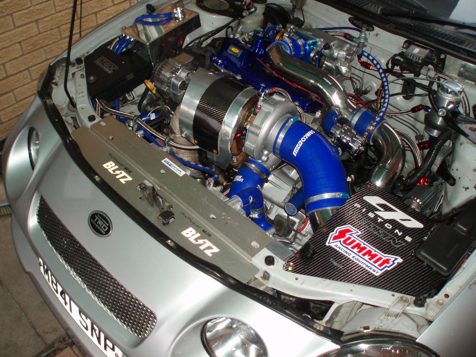
Cold air intakes create more horsepower because the draw in cooler air away from the engine. Denser air means more power, not to mention getting rid of the poorly designed air box. The CAI I made has a bypass filter in case water reaches the filter. The change in pressure will make the motor breathe from the bypass and prevent hydrolock. The main filter ends up above the mudflap and under the battery and radiator overflow to sheild from water and recieve air from the front damp. The filter is places sideways to draw in more air.

The intake was made from muffeler piping that was crush bent at a car shop near my house. I made it first out of PVC to get an idea of how to bend and cut the metal. PVC piping would be irrational to use seeing how there is now way to mount it and there is only 90 degree bends (hits hood). I told the guy what i was doing and just had him bend the peices, tried it out (had car apart outside his shop), had him bend it a little more, tried it out. He spent maybe 30 minutes working for me.

I get tons of horsepower and noticed the difference as soon as I rooled away from the shop. You can choose not to make it out of PVC first, but it gives the guy at the shop an idea of what you are talking about.

Shopping
PVC
2” diameter PVC piping
2 90° PVC elbow 2” in diameter (female/male)
1 90° PVC long turn elbow 2” in diameter (female/female)
Metal
1 flexible drain coupling (a.k.a. rubber plumbing nipple), 2” to 2”
K&N Filter for bypass

Required for both
1 flexible drain coupling (a.k.a. rubber plumbing nipple), 2” to 2”
K&N Filter

I will have filter numbers as soon as I find the boxes. I have them somewhere. (next couple of days I will have them)

Taking the car apart
Pop the hood and take a good look. It's beautiful. Yea, yea, yea. You will probably do this 10 times before you finish the intake (dont forget you car do the PVC part at home, put it back together, and part of the metal part at the shop, and the other part of the metal part at home.

Battery and Radiator Overflow
These will be taken off constantly. First take disconnect the battery and remove the bar that holds the battery in place as well at the black box. Twist the box aside and take the box out. (Almost everything on the car is a 10mm) Disconnect the hose and unscrew the radiator overflow. Take it right out.

Airbox
The stock airbox comes off some simply any 6 year old could do it. Ther clip comes off from the EFI by hand, 3 screws hold it down to the car inside the airbox, and the ghetto fender intake part falls out when the box is lifted out.

Making the PVC to get an idea
The intake is going to make a 90 degree turn from the EFI, down towards the front of the car, 90 degree, down to the bottom of the car, 90 degree facing the drivers side of the car. The intake actually runs along the side of the battery, but the black box needs to be twisted under the intake or to the side. The long 90 degree PVC will be for the turn that leads downward. Cut the PVC with a hack saw the sizes you need and try it. Its trial and error. Sanding the edges quickly will be required to make them slide together easily. Put the main filter on and make sure everything fits ok. The bypass filter and rubber nipples will be left to when you make it out of metal. For now, hold it up to the EFI.

Making it out of Metal
The intake will be made from 2.25 inch muffeler piping. A rubber nipple will need the be cut in half the attach the intake to the EFI Flush. The bypass filter will go anywhere above the batter facing the right. To connect it, another rubber nipple with actually seperat the intake into two peices. I drilled 4 tiny holes in the side of it and a big one to attach the filter attachment (you'll easily see when looking at the filter and attachment that came with it...I'll get a photo up). Show the bodyshop the PVC you made and have them bend and cut the first peice with the 90 degree. The ends will be needed to be expanded a little to fit with the rubber nipples (they know what to do...this was the first time anyone at the shop even done anything like this). Than make the down peice- fowards a little, long bend, down a little 90 degree bend to the drivers side. Looking at the PVC makes this process so much easier at the body shop. Don't forget that the ends will be needed to be expanded to fit.

Attatching it to something
I had the body shop weld a peice (a flat rod bent 90 degrees in half hotdogt way) that went from the intake to under the plastic the the battery went on. They drilled a hole in it and bolted it right there (a bolt already goes there so its perfect!). I had to take it out and do some grinding to that peice to make it flat at the end so the battery can sit on it. Ill get a pic up soon.

The End
Enjoy your intake. It was fairly simple to make and was also fairly cheap. It creates tons of power and makes the car not so restrictive and sluggish. Its better than trying to buy one because it has a bypass filter saving your enging from blowing. There is no cold air intake made for this car.


How to Install Aftermarket Gauges on Toyota Celica


The gauges I used are AutoGage’s mechanical 3-gauge cluster set. They are 2 1/16” in diameter. I suggest that only the 2 1/16” gauges are used because there is a lack of space in the center cluster. The cosmetics of the gauges don’t matter (white face, black face, chrome trim, black trim). The installation process will take approximately a whole day (at most, two days). One day can be used to make the Plexiglas panel and the other day can be used to install the gauges and fittings.

Tools needed:

  • Dremel
  • Dremel reinforced cutting wheel
  • Dremel sander
  • Sandpaper
  • Wrench set
  • Ratchet set

Materials:

  • AutoGage or AutoMeter mechanical gauges
  • Acrylic or Plexiglas sheet (about ? mm thin)
  • Metric adapter set (ex. Sunpro by Actron Metric Adapter Kit #CP7573)

I suggest reading the instructions that came with the gauges first. This is just a write-up by some kid who lost his instructions the very first day, and had to guess everything out.

Step 1: Cutting the gauge panel.
This is a relatively simple step. All you have to do is print out the pattern below, trace it onto the Plexiglas or acrylic sheet, and cut it with the Dremel.


Use the gauge panel that came with the gauges to trace the circles. Make sure all the gauges can fit snug into each hole. They need to be snug enough not to fall out and loose enough to be pushed in easily. Use the Dremel sander and sandpaper to smooth out any rough edges. If the panel doesn’t fit properly, do what you can to make it fit. Cut slits, sand away, etc.

Step 2: Fitting the gauge panel.
This is also a relatively simple step. Remove the center console trim by first removing the shifter trim and unscrewing two screws at the base of the center console trim. There are five tabs that hold the center console trim in place (3 on top, 2 on each side). The tabs on the gauge panel will fit into 2 crevasses under the bottom two screws of the radio assembly. They should fit snuggly. Otherwise, make them fit snuggly.

Step 3: Installing the gauge lines.
You do not have to drill another hole in the firewall. THERE SHOULD BE NO DRILLING INVOLVED! Under the dash above the steering column there is a hole already. A brass fitting conceals it. Stick your finger behind the brass fitting, and you will feel a hole. The hole leads to the engine bay where it resides under the ignition module. Snake the nylon oil and copper temperature lines to this hole. Make sure that you are able to step on the accelerator pedal without the lines interfering.

Step 4: Installing the gauges.
This step is explained in the instructions. I’m only going to go over some key points.

  • Put the gauges into the gauge panel first. It may be a bit tricky to get the wiring and hosing done, but it’s possible
  • Do not make sharp bends with the nylon or copper tubing.
  • The factory oil sensor is 27mm. If you have a 27mm socket, use it. Otherwise, be careful not to break the sensor off.
  • Be sure to tighten all bushings on the oil line before starting the car.
  • The water temperature sensor fitting isn’t included in the kit. You’ll have to have one custom-made. I placed mine on the water outlet housing where Toyota installed two 17mm plugs. I just removed one of the 17mm plugs, and place my temperature probe there. You can also design a T-fitting for the upper radiator hose.
  • When wiring the light for the water temperature sensor, reverse the polarities. That means, hook the power wire on the gauge to a ground wire on the car and the ground wire on the gauge to a power wire on the car. This is because the copper tubing on the water temperature line acts like a ground. If you don’t do this, expect blowing a 15A fuse.
  • The voltmeter is hooked up to my cigarette lighter.
  • Lighting wiring in my car as follows:
  • One +/- hooked up to the cigarette lighter light.
  • 2 +/- hooked up to the ashtray light.

Step 5: Double check.
Check to see that all lines are secure and fitted. Make sure there are no exposed electrical wires. Once you are sure, it’s time to fit the gauge panel into the dash. The two tabs will rest between the bottom two radio screws and above the center console trim tabs. It will be tricky to secure the gauge panel there, so if problems arise, use either some school glue or some tape (for temporary purposes). You won’t need to use tape or glue, but if you do, experiment at your own risk. The gauge panel should hold in place once the center console trim is fastened. If not, then check to see if the Plexiglas or acrylic is too thick. Other than that, you're done. Enjoy knowing how your engine behaves. Don't get too distracted.


How to Advance Your Ignition Timing on Toyota Celica

This is applicable for all Celicas. The test car used is a 1991 Toyota Celica GT with the 5S-FE engine. Other's may be similar in results. I cannot be held responsible for any damage that occurs to the engine or the car while this procedure is followed. Everything is explained to the best of the author's knowledge. Refer to a Celica manual for more infomation about ignition timing.


Intro: Factory timing for all 90-93 normally aspirated Celicas (ST, GT, and GT-S) is 10? before top dead center (BTDC). This means when the crankshaft angle of the number one cylinder reaches 10?, the spark plug will fire. It fires before it reaches top dead center (TDC) because the flame front takes time to fully combust and push the piston downward.

Retarded timing: If the ignition timing on a car is retarded, then less power is made because the air/fuel mixture doesn't completely combust during the compression/combustion cycle. The flame front completely combusts after the piston has started its power stroke. This results in a loss of power.

Advanced timing: If the ignition timing on a car is advanced (to a certain degree), slightly more power is made because the air/fuel mixture is given time to fully combust and to allow the plug spark to travel. When the air/fuel mixture completes combustion, there is enough power created to slam the piston downward.

Over-advanced timing: If an improper grade of fuel is used combined with an over-advanced timing setting, the effects of detonation can damage the engine. Detonation is when the air/fuel mixture combusts too early or too quickly during the compression stroke. The flame front collides with the upward-stroking piston. Pressure in the cylinder becomes increasingly high. Temperature rises to extremely dangerous levels. This results in engine damage.

Octane Fact: The recommended fuel grade for all the normally aspirated Celicas is 87 octane. Everyone should know that octane is a knock-inhibitor. What octane does is slow down the combustion process. So, it burns slower giving the piston time to compress the mixture and the spark to travel. The power comes from the full combustion of the air/fuel mixture. Higher octane gas + advance timing = more power. I read somewhere about a guy with an N/A Supra who advanced his timing to 25? BTDC and used 120 octane gas. He claims to have made an extra 100 WHP. I find it hard to believe. The power curve for ignition timing is like a parabola: only at one single point will there be a peak power position for both torque and horsepower.

How do I advance my timing?


First, obtain the necessary tools.

  • A timing light
  • 12 mm socket
  • A small piece of wire or paper clip

Make sure your car is at operating temperature. You cannot check the timing correctly if your car has been sitting outside cooling down all day. It must be at operating temperature.

Step 1: Jump terminals
Locate the DIAGNOSIS plug. It's a gray box on the driver’s side by the windshield wiper motor. Open it up, and jump the TE1 and E1 terminals with the wire or paper clip. You'll know when it's jumped when you turn the key to the ON position, and the CHECK ENGINE LIGHT is flashing the "NO TROUBLES" code (1 flash, pause, 1 flash, pause, 1 flash, pause, etc).

Step 2: Hook up the timing light
The timing light has instructions. Read them. Otherwise, listen to me. Red clip goes on positive side of battery; black goes on negative side. That black clippy-thingy goes on the number 1 spark plug wire. Simple.

Step 3: Checking the base timing
Now, you have the terminals jumped and the timing light hooked up. Start the car. The car should sound like it's lugging and the idle should be lower than normal. This means you've jumped it correctly. Locate your underdrive pulley. There are timing notches above the pulley. Point and "shoot" the timing gun at the pulley and notches. You will see what your base timing is currently set at. Make sure you’re viewing the notches dead on and not at an angle. Stand above the engine or to the left on the passenger side to have a dead center straight-on view of the crankshaft pulley and the timing notches.


Step 4: Adjusting
Take the 12mm socket and loosen the holding bolt on the distributor. You can do this while the engine is running as long as you don't pull the distributor out (duh!). Just loosen it enough so that you can move the distributor. Rotate the distributor upward (clockwise) to advance timing; rotate it downward (counter clockwise) to retard timing. Keep using the timing gun to see where you've adjusting the timing to.
Henry’s Corner. I’ve done various degree setting to see what is the best and most efficient degree to set the ignition timing at. I was running with 93 octane for each test.

25?+ BTDC: Only good on a cold winter day. Otherwise, crappy idle.
20? BTDC: A little better than 25? BTDC. There's still some inconsistency in the idling, but it's not serious.
17?-19? BTDC: I haven’t tried it yet. Feel free to tell me the results.
16? BTDC: Pretty good for now. That’s what I have it set at as of December 20, 2000.
12?-15? BTDC: I didn’t have any problems, but I wanted to advance it to 16? BTDC to see how far I could push it.
11? BTDC: Seems just too close to 10? BTDC for any kind of change.
10? BTDC: That’s factory setting. I’m tired of factory. I need change.
7? BTDC: Stupid, Henry; that’s retarding your timing.

I cannot confirm 100% why crappy idle occurs. I said it was due to detonation and the knock sensor was picking up the readings. But there’s a problem: 1990-91 5S-FE’s didn’t have knock sensors… at least that’s what I read. Also, I started to tap on my engine with a hammer, and the timing didn’t retard. Despite that, for some reason when I set the timing to 20?-25?+ BTDC, the timing just retards on it’s own like there was a knock sensor doing its job. I did check my plugs for the effects of detonation and there was no damage at all.
My friend told me that the ECU knows that the base timing is 10? BTDC, and it will try to retard the timing to 10?. Sounds right, but I have evidence that disproves the theory: I'm at 16? BTDC and my car isn't experiencing bad idle.


Step 5: Finishing up
When you've set the timing to where you like it, tighten the 12mm bolt, and turn off the car. Remove the jumper wire. You may start the car again to see what the "adjusted" timing is. Then, remove the timing gun.

Is this mod worth it?
If and only if you're trying to squeeze every bit of power from your car and you're willing to use a higher grade of gas to do it. I can afford to use a higher grade of gas. I know some people can't, so it may not be worth it to them.
How much of a power gain should I expect?
Hopefully, you gain some mad horsepower so you can beat Civic Si's, but I doubt that'll be the case. I read that adding 1? of advance produces 2 horsepower to the wheels. Of course, this is only a guideline, and it varies from car to car.